Summary
 An urban development that includes 947 residential allotments is proposed for a site at Fern Bay adjacent to Nelson Bay Road near Newcastle in New South Wales. The site is located in the local government area of Port Stephens. This report examines the topography and geology of the site and develops a stormwater management strategy. The stormwater management strategy incorporates the water sensitive urban design treatment train philosophy for urban development at the site. The basis of the stormwater management strategy is opportunistic utilisation of the high infiltration capacities displayed by soils on the site.
It is proposed to use pipe drainage, infiltration trenches, roads with one-way cross-falls, bio-retention swales, gross pollutant traps, infiltration swales and infiltration trenches to manage stormwater quantity and quality at the site.
The stormwater management strategies proposed in this report will protect the proposed urban development from flooding whilst mitigating potential stormwater impacts of urban development on receiving environments. The strategy will not require maintenance efforts in excess of the requirements of traditional pipe drainage systems.
The use of 3 kL rainwater tanks to supply domestic toilet, laundry and outdoor water uses, and water efficient appliances will reduce household water use by about 50%. This equates to an annual reduction in mains water demand for the entire site of 101 ML.
Introduction
Urban Water Cycle Solutions was commissioned by Aspen Group Pty Ltd to develop an urban water cycle management strategy for the proposed urban development at Fern Bay. This strategy also employs water sensitive urban design (WSUD) techniques. The proposed urban development includes about 950 residential allotments and will be situated in the local government area of Port Stephens.
The site of the proposed urban development has a land area of 205 Ha. The development site has an undulating topography that consists of sandy soils with low lying areas adjacent to Nelson Bay Road and is underlain with an unconfined aquifer. Traditional stormwater drainage practices may be unsuitable for this site necessitating the use of water sensitive urban design (WSUD) approaches to deliver sustainable stormwater management solutions.
This investigation considered data and stormwater management proposals from previous studies and proposes an integrated water cycle management strategy that is consistent with the natural water cycle processes currently operating at the site.
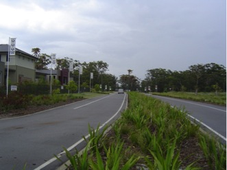
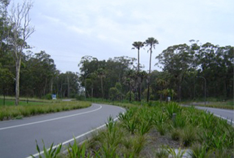
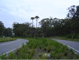
Main boulevard in the Fern Bay development showing central bio-retention swale and one way cross fall road
Water Cycle Processes at the Site
A schematic of the water cycle processes operating at the proposed development site is shown in the Figure below. Stormwater runoff from the northern areas of the site discharges to low lying areas adjacent to Nelson Bay Road and ultimately evaporates from the low lying areas or flows via culverts under Nelson Bay Road towards Fullerton Cove.
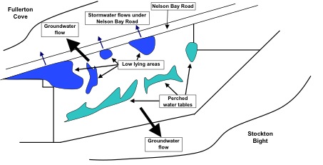
Schematic of the water cycle processes operating at the site
Stormwater runoff from southern and internal areas of the site discharges to a series of perched water tables located between sand dunes at the centre of the site and ultimately evaporates to the atmosphere. There may be some surface water connectivity between the internal perched water tables and the low lying areas adjacent to Nelson Bay Road. The site is underlain by an unconfined aquifer that can maintain water levels in low lying areas and allows groundwater to drain from the low lying areas and perched water tables towards Fullerton Cove and Stockton Bight. Water is also lost from the soil profile and the aquifer via evapotranspiration processes.
Geology and Soil Types
The geology at the site consists of a topsoil layer, about 0.2 m thick, of silty sand over a sand layer with a thickness that varies from 13 m to 27 m that overlays sandy clay. The sand layers at the site are underlain by rock at a depth of about 60 m. Peat has been found in the low lying areas adjacent to Nelson Bay Road.
The sand layer is made up of medium to fine grained sand that contains few fine particles. High infiltration rates should be expected from this sand layer although the silt content in the topsoil layer may impede the infiltration of water into the sand layer. Historical observations indicate that 75% to 90% of rainfall falling on the site is infiltrated into the sand layer.
Groundwater Considerations
Previously studies indicate that the site overlays an unconfined aquifer with depths up to 15 m. Groundwater at the site flows northeast towards the Stockton Bight and southwest toward Fullerton Cove at 16 – 22 m2/day. All studies show that groundwater levels vary with ground surface levels with groundwater levels more likely to be higher in locations where the ground surface levels are higher.
Flooding Issues
The Lower Hunter Flood Study has reported that the 100 year average recurrence interval (ARI) flood level in the lower Hunter River is 2.0 m AHD. Port Stephens Council and other organisations have accepted this flood level for the site. However it should be noted that the Hunter River Estuary and Nelson Bay Road will separate the site from the effects of Hunter River flooding. Nelson Bay Road forms a barrier to flood waters whilst the expanse of the estuary system will diminish the height of flood levels. Culverts located under Nelson Bay Road will allow some of the flood waters to enter the site but, mostly, the culverts will allow stormwater to discharge from low lying areas near Nelson Bay Road towards Fullerton Cove.
Water Quality Issues
Urban development usually increases the proportion of impervious surfaces in a stormwater catchment and includes highly efficient drainage systems (pipes and channels) that increase runoff volumes and peak discharges to a receiving environment whilst decreasing or eliminating infiltration of rainwater into soils. Increases in stormwater runoff and efficient conveyance systems may also convey pollutants that are generated by urban development to receiving waters creating adverse environmental impacts.
The use of traditional pipe drainage and regional basin methods will result in the discharge of stormwater runoff towards Fullerton Cove. This action is likely to change the hydrological regime in the coastal wetlands situated between Fullerton Cove and the site. Increased loads of contaminants may also be discharged to this area. The combination of changed hydrological regime and contamination may have harmful impacts on the coastal wetlands. Note that coastal wetland number 821 protected by State Planning Policy 14 is located in this area.
The Stormwater Management Strategy
The topography and geology of the site indicated that stormwater should be managed in a series of small stormwater management precincts. Stormwater quality and quantity are managed in each stormwater precinct that contains about 50 to 100 dwellings. The area of each stormwater management precinct will be governed by topography and town planning issues.
A WSUD stormwater treatment train philosophy was be employed within each stormwater management precinct and between the precincts. A flowchart of the stormwater management strategy is shown in the following Figure.

Flowchart of stormwater management processes within each precinct
Stormwater runoff from roofs of dwellings situated at the high side of roads is discharged to bio-retention trenches placed under swales located in the road reserve. The grass swales within the road reserve will collect stormwater runoff from road pavements with one-way cross-falls and excess stormwater runoff from allotments. It is expected that the majority of rain falling on allotments will infiltrate to the aquifer. Stormwater runoff that concentrates in the swales will infiltrate into the bio-retention trenches below with excess stormwater conveyed to an inlet pit.
The inlet pits distribute stormwater flows into the gravel bio-retention trenches which capture sediments, debris and litter. Stormwater is distributed within the gravel bio-retention trenches by an agricultural pipe allowing infiltration to the aquifer along the length of the trench. The trenches and the agricultural pipes convey excess stormwater toward infiltration swales and basins. Stormwater conveyed along infiltration swales and stored in infiltration basins will be discharged over a period of time into the aquifer.
Stormwater runoff from roofs of dwellings situated at the low side of roads is discharged to inter-allotment pipe drainage systems that will convey stormwater to the nearest bio-retention trench system. Roof runoff will be discharged into on-site infiltration trenches in situations where access to a street or inter-allotment drainage system in not possible.
Street Drainage Systems
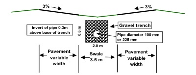
Local roads within each stormwater precinct consist of road pavements with one-way cross falls that discharge stormwater runoff to bio-retention swale systems (see Figure below). The bio-retention swale system consists of a shallow grass swale with a width of 4 m and a gravel trench (0.45 m wide and 0.6 m deep) that contains a 100 mm diameter agricultural pipe.
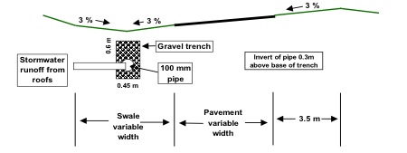
A typical local road cross section that includes a bio-retention swale
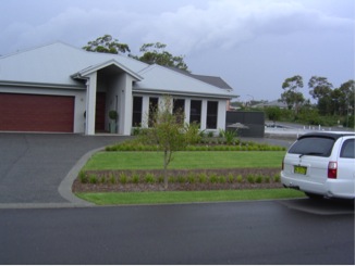
The interface between road reserves with bio-retention swale and housing
Stormwater runoff from road and allotment surfaces is directed via overland flow to the swale system and infiltrated through the swale surface into the gravel trench. The trench contains gravel with a nominal diameter of 20 mm to 30 mm that is surrounded by geofabric. Surface flows in the swale are directed to inlet pits that discharge excess stormwater into the gravel trench (see Figure below). Within the gravel trench stormwater infiltrates to the surrounding soil and flows downstream via the 100 mm diameter agricultural pipe. Roof runoff from allotments on the high side of streets is discharged via rainwater tanks into the gravel trenches. The bio-retention swale system will be designed to cope with all storm events up to the 100 year ARI events. The finished surface level at each road boundary should be 100 mm about the expected maximum stormwater level in the bio-retention swales during 100 year ARI storm events.
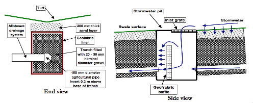
Bio-retention swale and inlet pit details

The interface between road reserves with bio-retention swale and housing
Collector roads within the development that have dual carriageways will have pavements that fall towards a bio-retention swale system located at the centre of the road reserve (see Figure below). The gravel trench and agricultural pipe system situated below the swale allows stormwater to infiltrate to the aquifer whilst conveying excess stormwater to the nearest low point. At low points the bio-retention trench system will discharge excess stormwater to nearby infiltration swales, basins or the existing low lying areas.
Bio-retention swale at the centre of dual carriageways
Stormwater pipes used to convey stormwater from bio-retention swale systems under roads was designed to cope with runoff from all storm events up to and including the 100 year ARI events.
Allotment Drainage Systems
The drainage system discharging roof water into the bio-retention swale system will have a small pit with a grated inlet installed at the site boundary. This will allow stormwater to surcharge from the roof drainage system in a situation when the gravel trench below the swale in overwhelmed by stormwater and allow inspection and cleaning of the drainage. A diagram of this system is shown in the following Figure.
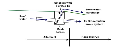
Details for the connection of roof drainage to the street drainage system
In situations where it is not possible to discharge roof water to a street or inter-allotment drainage system, roof water can be discharged to an infiltration trench. The infiltration trench will be filled with coarse gravel (nominal diameter of about 30 mm) surrounded in geotextile fabric, have an inflow pipe, a small pit with an inlet grate that acts as a sediment trap, a perforated distribution pipe and is placed under a 150 mm layer of sand or loam. The sediment trap prevents clogging of the trench with sediment, leaves and debris, and the geotextile fabric cleanses water as it percolates through the bottom and walls of the trench to the surrounding soil. Designs for infiltration trenches can vary provided they contain the basic principles listed above. A typical design is shown below in the Figure below.
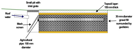
Details of an infiltration trench used to capture roof water on allotments
Infiltration Basins and Swales
In a situation where excess stormwater runoff passes through the WSUD treatment train, it will discharge into an infiltration swale or basin. The infiltration basin collects and stores stormwater until it dissipates to the surrounding soil via infiltration and to the environment via evaporation. These basins remove a portion of stormwater runoff thereby reducing stormwater peak discharge and volume to downstream catchments. These processes also improve the quality of stormwater discharged to the receiving environment.
The infiltration basin will be designed as a depression with good grass coverage over a layer of coarse gravel surrounded by geotextile fabric. A 150 mm layer of topsoil is usually placed between the gravel layer and the grassed surface. Stormwater entering the basin is filtered to remove sediment, leaves and debris by sediment traps, vegetated areas or GPTs. Stormwater fills the basin and the gravel layer, percolates to the soil and overflows to the low lying areas when the basin fills. A schematic of an infiltration basin is shown in the Figure below.
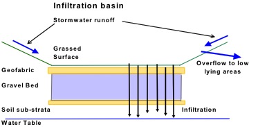
Design of the infiltration basin
The infiltration basins will consist of sub-surface and surface storage areas. The sub-surface storage will be filled with 20 mm to 30 mm nominal diameter gravel surrounded by geofabric. Stormwater will be stored in the void spaces between the gravel and also infiltrate into the surrounding soil. Stormwater from the subdivision drainage system will be directed to the sub-surface storage area via a grated pit that also allows surcharge into the basin. The surface storage area consists of a landscaped area surrounded by bund walls that will contain stormwater volumes that are in excess of the storage provided by the sub-surface storage area. A schematic of an infiltration area below the basin is shown in the Figure below.
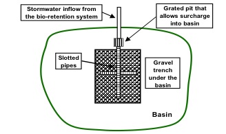
Schematic of a plan area of an infiltration basin
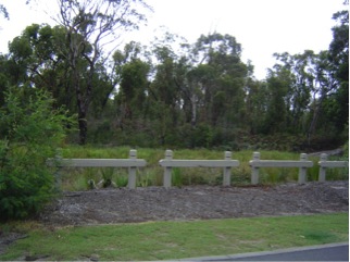
Infiltration basin